Using Properties as Pins
With Reality 4.25, properties in the nodes can be manipulated through node graph. Let's work on COLOR CORRECTION node and how we can manipulate its properties by using these properties as pins and use them in the node graph :
Starting an Empty Project
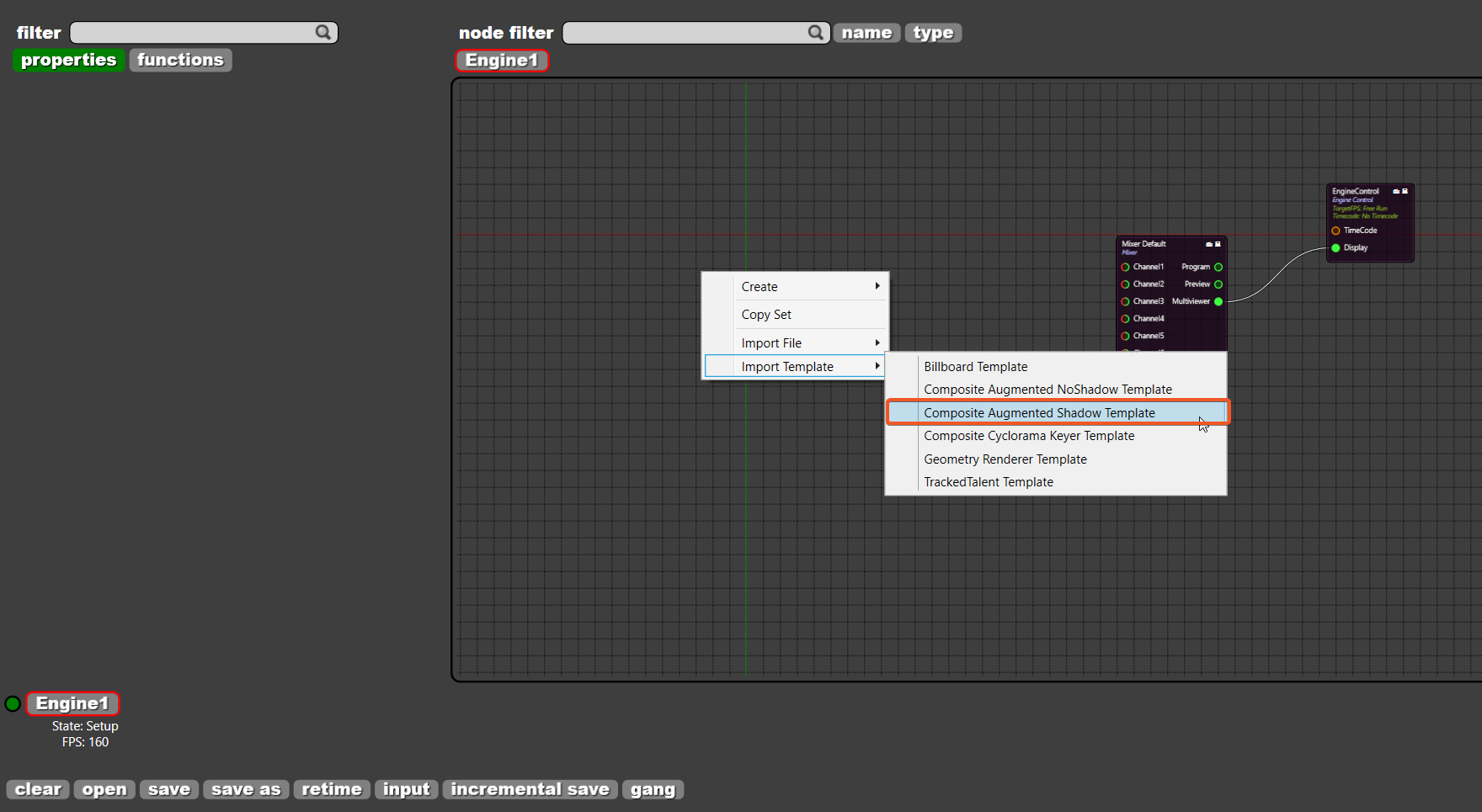
When you are working on a project file or running a studio, click on Reality Control icon on Windows Desktop to launch Reality Control and press F7 to launch Reality Setup. On Reality Setup, right-click on the node graph, go to Import Template > Composite augmented with shadows to import one of the default templates in Reality:
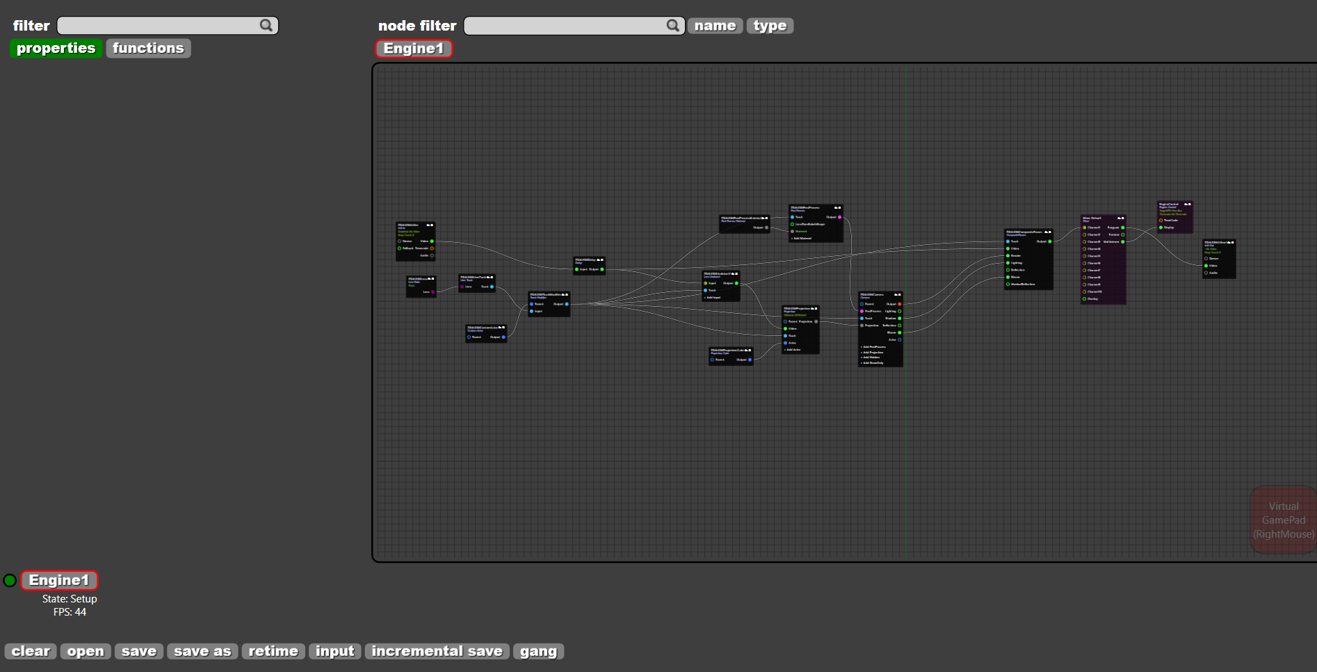
And the set will be imported and the node graph should look like below:
Adding Color Correction Node
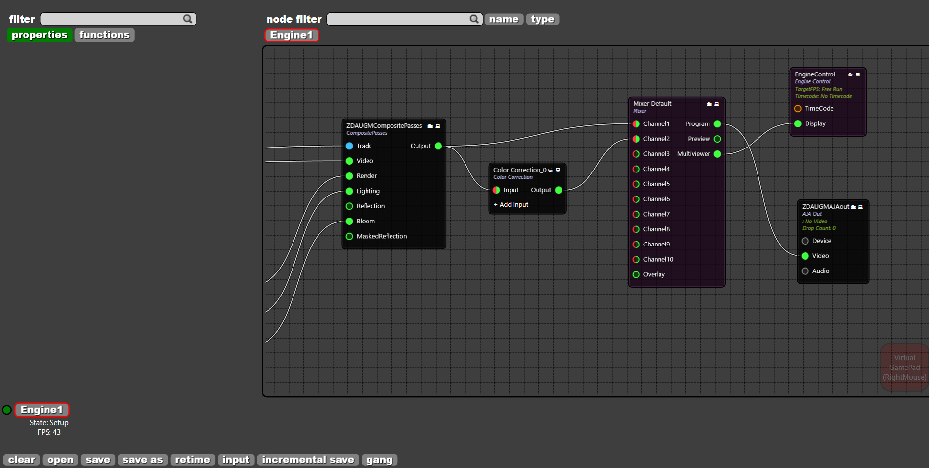
Add a COLOR CORRECTION node between COMPOSITE PASSES and the MIXER DEFAULT nodes:

And connect OUTPUT pin of the COMPOSITE PASSES to INPUT pin of the COLOR CORRECTION. Connect OUTPUT pin of the COLOR CORRECTION to the MIXER DEFAULT node's CHANNEL2 pin:
Converting Properties to Pins
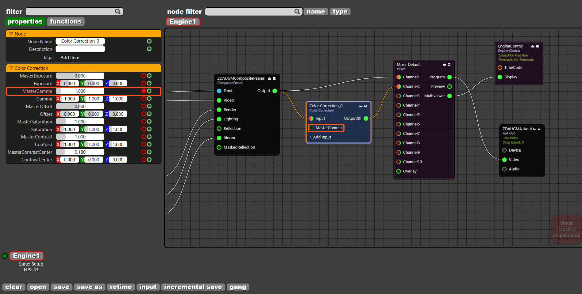
Click on the 

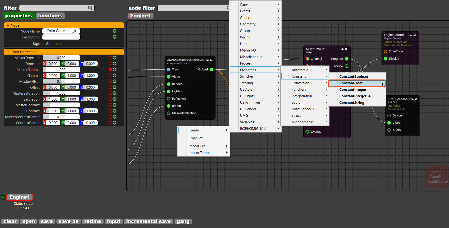
Adding Properties Nodes
The properties of the nodes can be changed via the new node category named as "Properties". To change the properties of the COLOR CORRECTION node, right-click on node graph and go to Create > Properties > Constant Float and add a CONSTANT FLOAT node to the node graph:
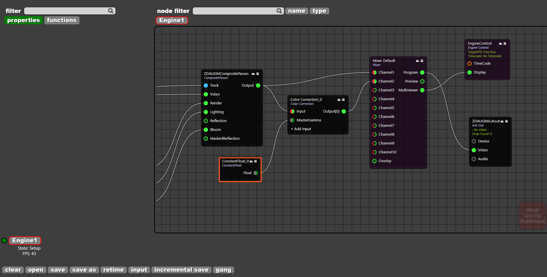
See that CONSTANT FLOAT is added to the node graph. Once added, connect it to COLOR CORRECTION node's MASTER GAMMA pin and note that the same types of inputs are marked as the same. Here, float property is marked as green and gray. Remember that if the input types mismatch. the pins cannot be linked to each other:
Using a Float Property as Pin
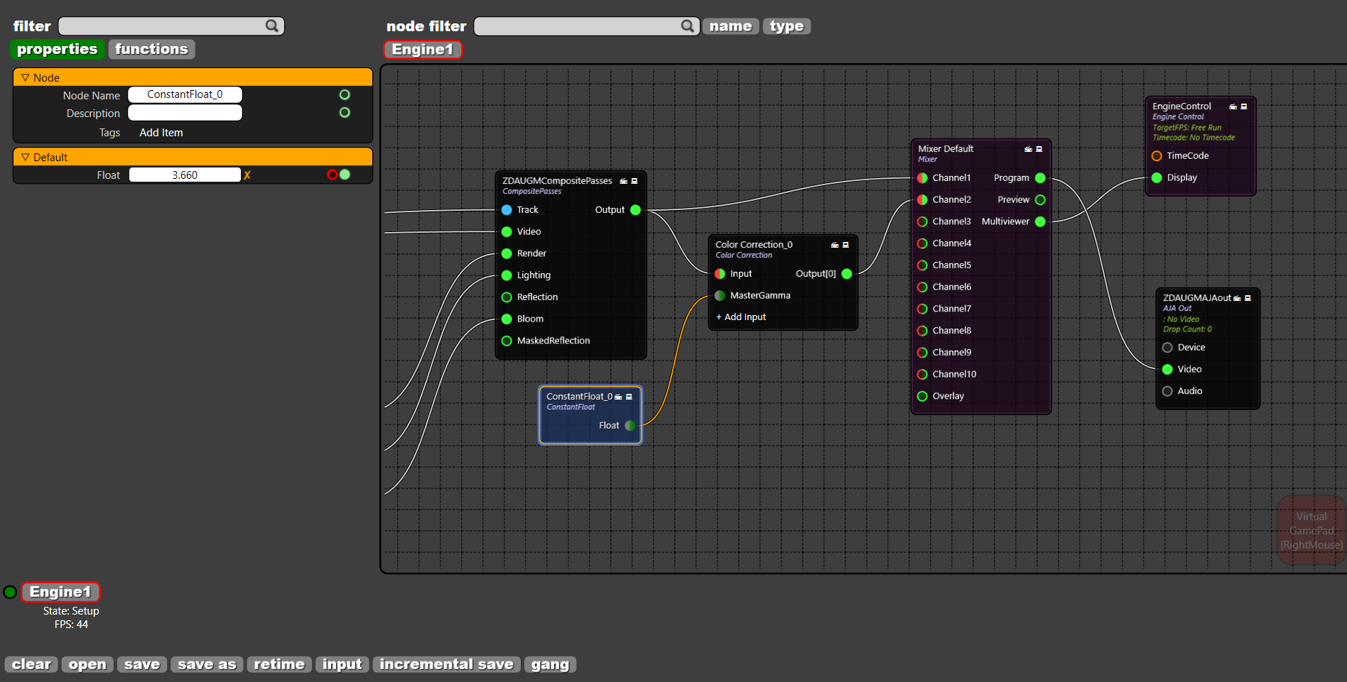
Change the FLOAT property of the CONSTANT FLOAT node:
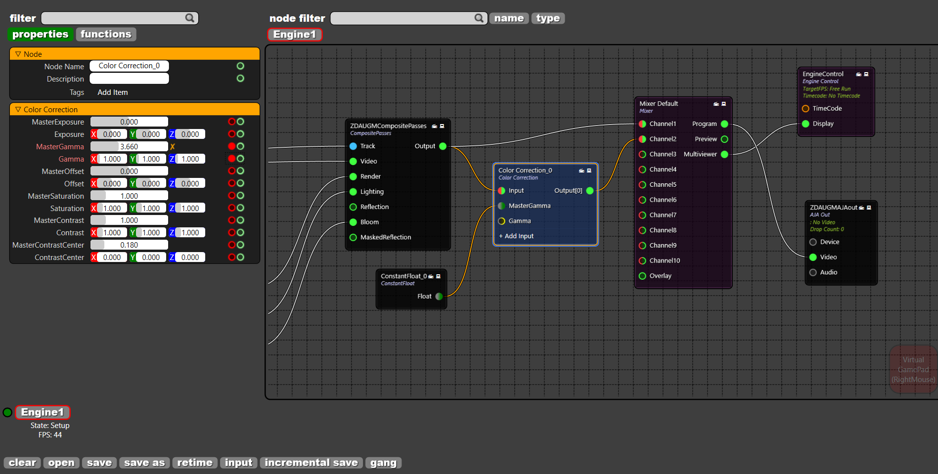
See that the float value changes the output on CHANNEL2:

Using Vector Property as Pin
Vectors (3 dimensional) can also be converted to pins. By clicking on
Add a MAKE VECTOR node by right clicking on the node graph and Create > Properties > Struct
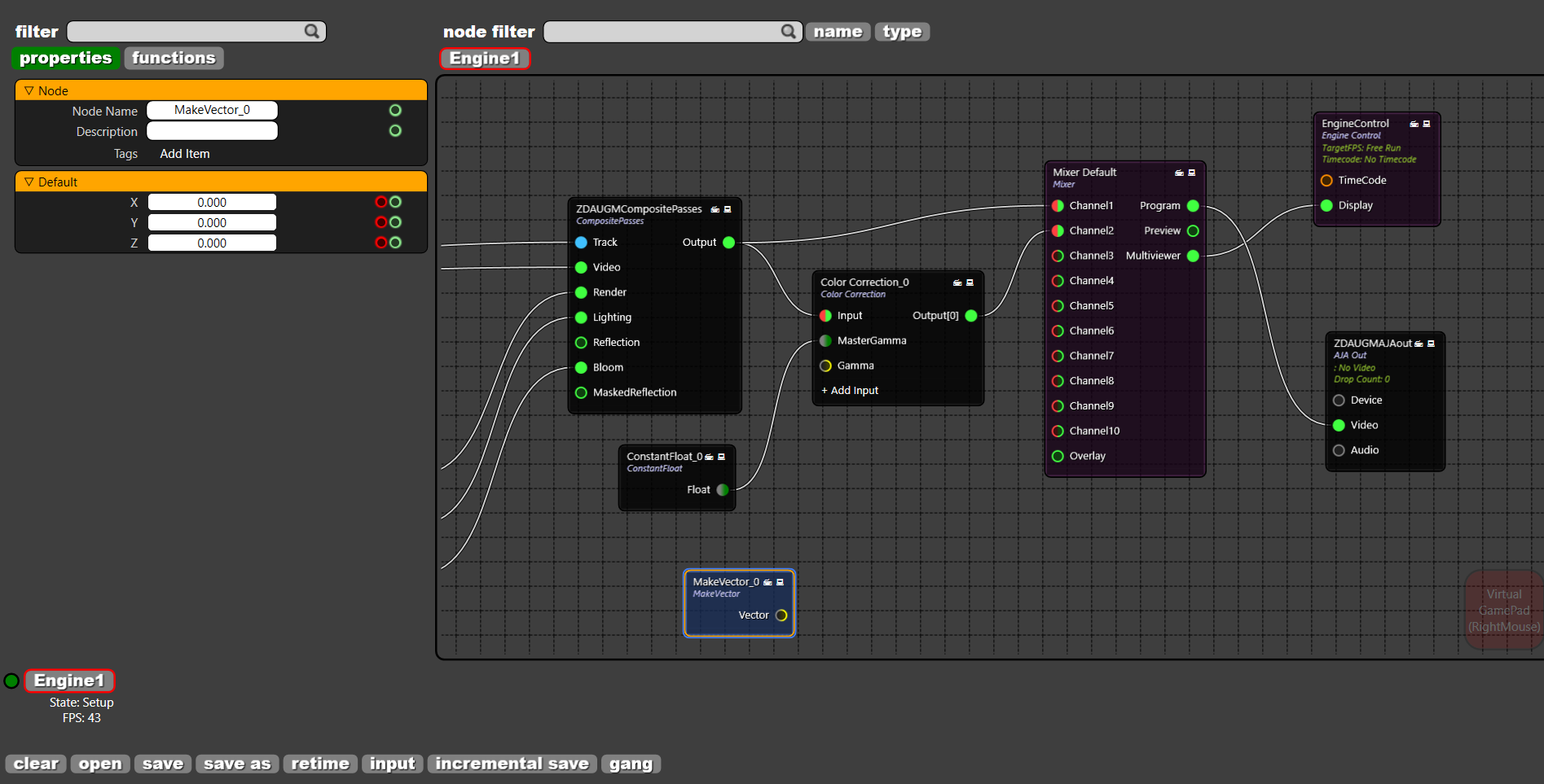
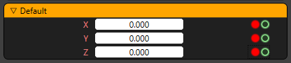
There are 3 properties marked as X, Y and Z. Click on
Create three CONSTANT FLOAT nodes and connect each of them to MAKE VECTOR node. Connect the VECTOR pin of the MAKE VECTOR node to the GAMMA of the COLOR CORRECTION node:
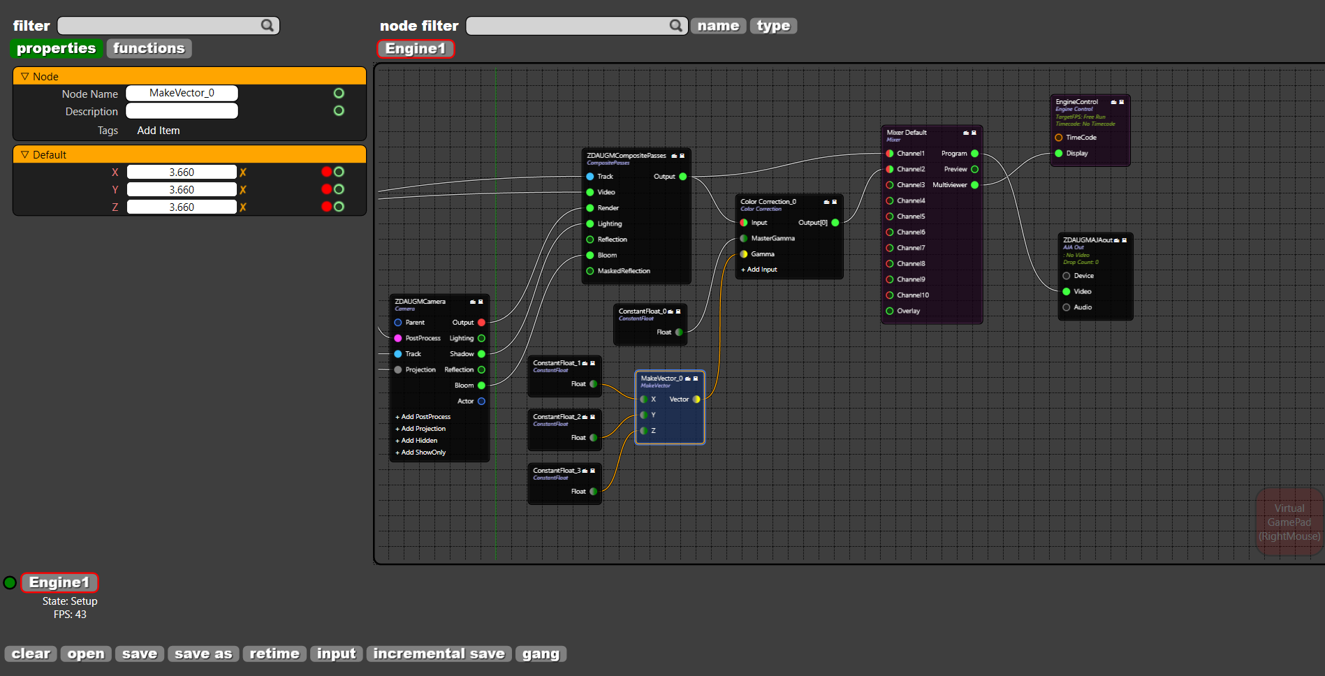
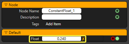
Go to each CONSTANT FLOAT to change their values:
See that as the FLOAT values change the image on the CHANNEL2 changes:

Changing Input Types
It is possible to convert between different input types. Go to Create > Properties > Constant > Constant Integer to add a CONSTANT INTEGER node and go to Create > Properties > Conversion > IntegerToFloat and add a INTEGERTOFLOAT node. Connect the CONSTANT INTEGER node to INTEGERTOFLOAT node. And connect the INTEGERTOFLOAT node to CONSTANT FLOAT to finish the conversion pipeline:
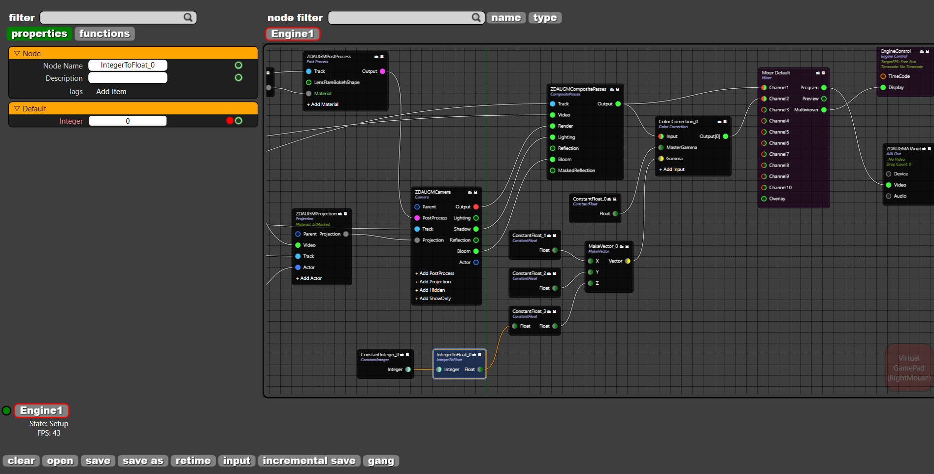
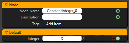
Change the INTEGER property of the CONSTANT INTEGER node:
And see that the changing integer value makes difference on the CHANNEL2:

As this tutorial suggests, it is possible to manipulate the properties on the node graph.