Projection Cube
Purpose of the Projection
PROJECTION CUBE helps you define a virtual area in your set design’s 3D space (Volume). Your camera signal from the Keyer or camera inside your studio is projected directly on the PROJECTION CUBE.
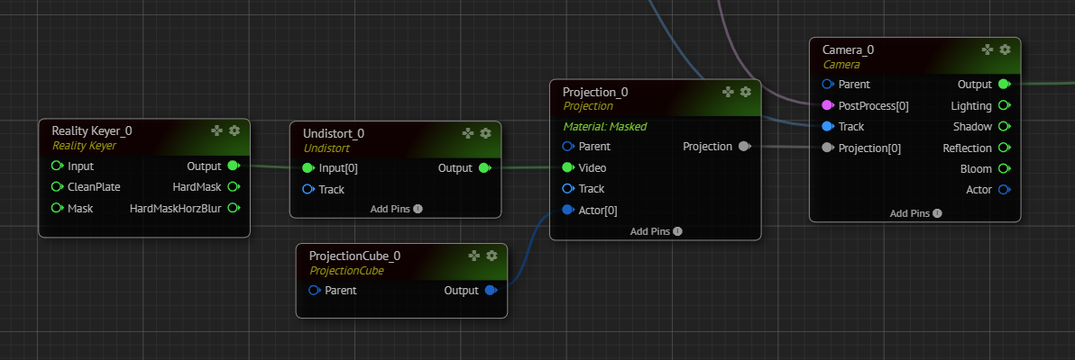
For the keyed pipelines, after creating the key from the image coming from the broadcast camera using the REALITY KEYER node, we have to connect the processed RGBA image to the PROJECTION CUBE node's VIDEO input pin after undistorting the image. Also, connect your tracking device's OUTPUT to the TRACK input pin of the PROJECTION CUBE node. And the PROJECTION CUBE`s OUTPUT pin should be connected to the ACTOR pin of the PROJECTION CUBE as shown below:
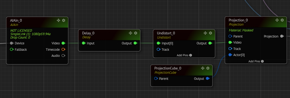
If you are using an augmented pipeline, you have to connect a delayed and undistorted output to the VIDEO pin of the PROJECTION CUBE . Also, connect your tracking device's OUTPUT to the TRACK input pin of the PROJECTION CUBE node. And the PROJECTION CUBE's OUTPUT pin should be connected to the ACTOR pin of the PROJECTION CUBE as shown below:
Projection Cube
Reality is compositing the incoming keyed video in 3D space. To accomplish this, we need to define the “Boundary Cube,” called PROJECTION CUBE.
The image coming from the Reality Keyer will be projected onto the “Projection Cube” using the TRANSFORM of the TRACK node and the FOV property of the CAMERA node.
It is essential to define the Projection Cube's boundaries accurately. When the projection cube is visible, make sure to move the camera to all possible shooting locations within the physical studio. It is also essential to stay inside the Projection Cube at all times.
Using this method, there is no requirement for 2D layering and rendering techniques such as “Screen Space Reflections” to become possible.
Adjusting the Projection Cube Position
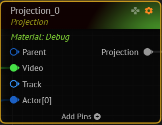
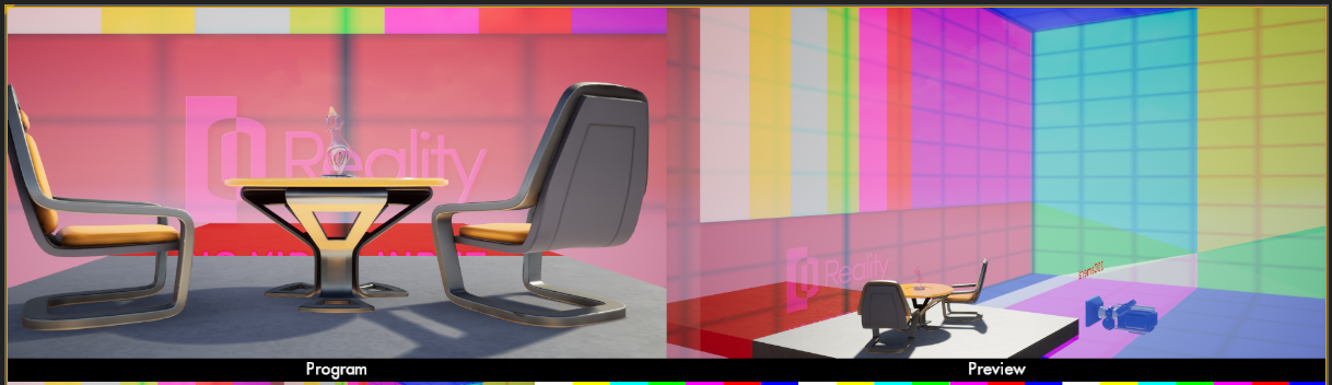
To quickly seeing what we are doing in 3D space with our “Projection Cube,” we can set the PROJECTION node to “debug” mode. When the PROJECTION node is in debug state, it draws a checkerboard pattern on all the faces. This mode lets you easily see the depth and height of our projection cube. We should change the relative location of the PROJECTION CUBE using the TRANSFORM property of the TRANSFORM.
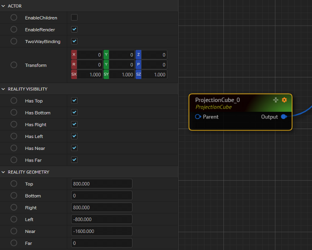
Then, the FAR, LEFT, RIGHT , and TOP properties are used to set the PROJECTION CUBE's dimensions. The Z of the TRANSFORM property should be used if your Virtual Set’s floor is not set at 0. You increased the Z value to set the height of the ground plane of the PROJECTION CUBE.
The LEFT property can only be used when the physical “Cyclorama” ground is above your tracking camera's ground plane in terms of Z coordinate.
Viewing the Projection Cube from Outside
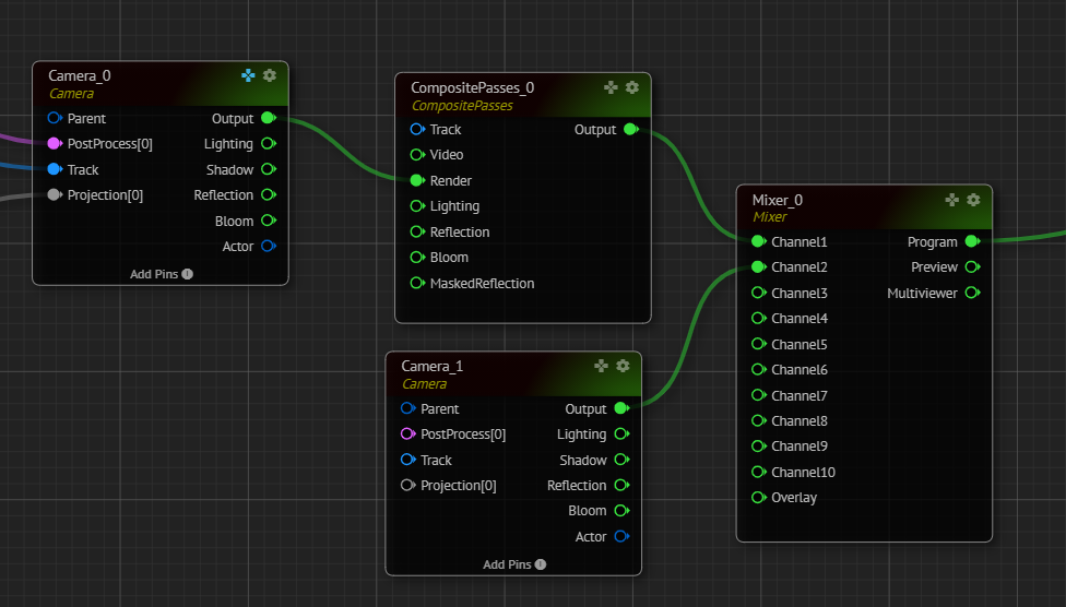
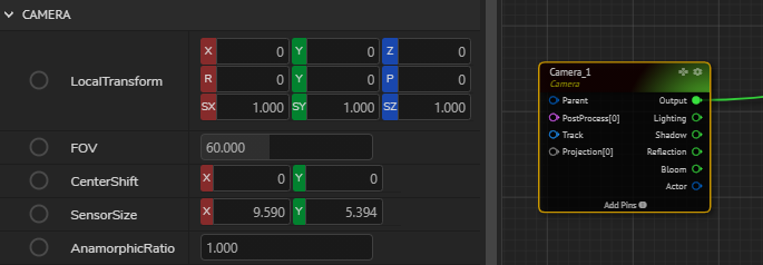
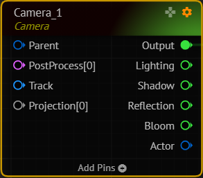
To view the Projection Cube from outside. Please add a second CAMERA node to the system as shown below and connect this to CHANNEL2 of the MULTIVIEWER node and enable the RealityHub Gamepad of the second CAMERA node.
By using the Gamepad feature, change the LOCAL TRANSFORM of the CAMERA node.
And put the first CAMERA node into Debugging Mode.
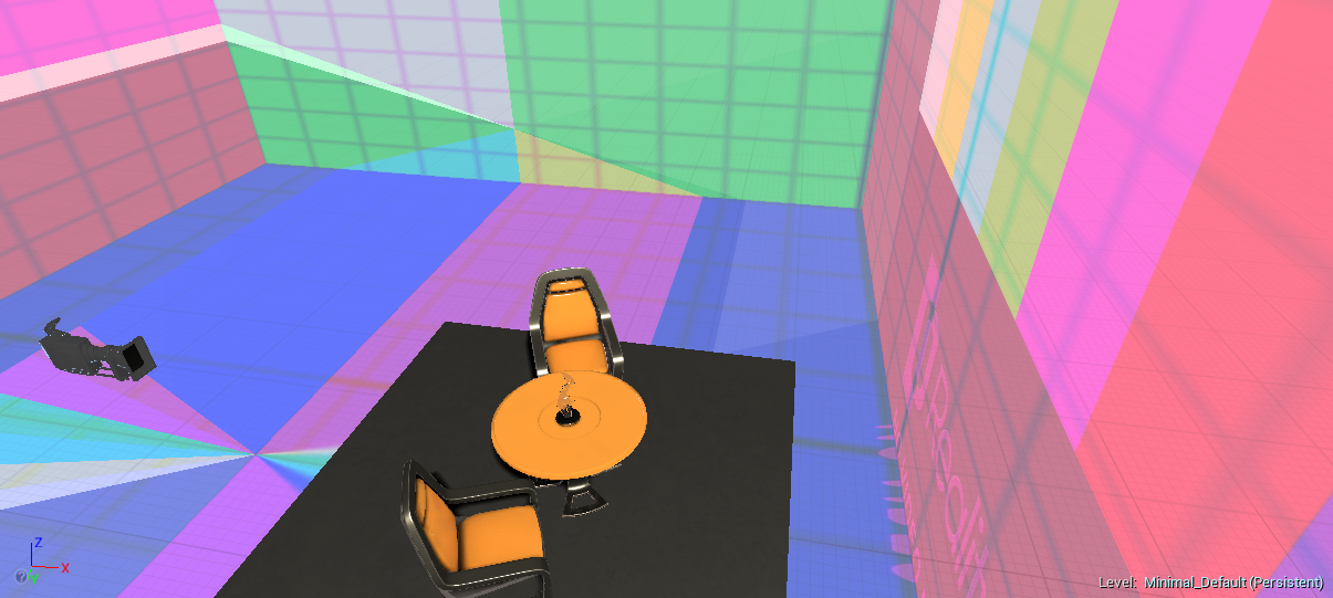
See that the camera appears in the set as shown below:
And see that on CHANNEL2 , you start seeing the Projection Cube and the first camera from outside. This action provides a broader and better understanding of the Projection Volume.