Knowledge Base
Below you can find short answers for frequently asked questions, improving your everyday Reality knowledge and allowing you to use Reality in the best possible way. Some of the answers have links that can lead you to in-depth documentation for that topic.
Answer |
|---|
As Reality is an Image Based Keyer, the image that is taken from a specific camera, with a specific lens which might has a different Lens Center Shift Value will differ in each separate system. We recommend that you take the clean plates separately for each engine to make sure that you get the best result from each engines. |
Answer |
|---|
As Reality uses Image Based keying, it is important to take the captures to be used as Clean plates while you have the general lighting. It is advised to test and compare the result and to take specific captures for Clean plates if you observe a drastic change in the keying quality when you change the lighting setup in your physical studio. But if you are using just talent lighting in close shots, this might night be a need. Please refer to link here for more information on Reality Keyer. |
Answer |
|---|
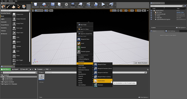
This is a step-by-step guide to make FlyCam virtual camera movement(s) including a sample action file.
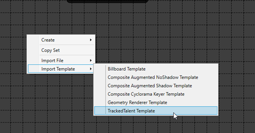 Figure 1: Reality Setup application.
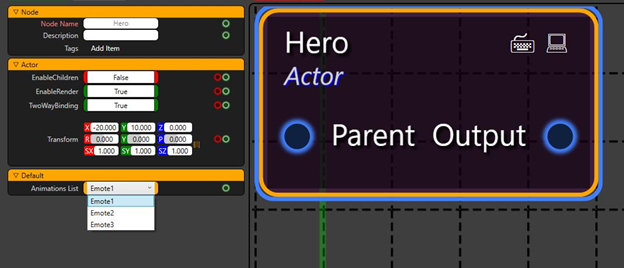
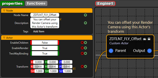 Figure 2: Custom Actor node for Fly Offset and its properties.
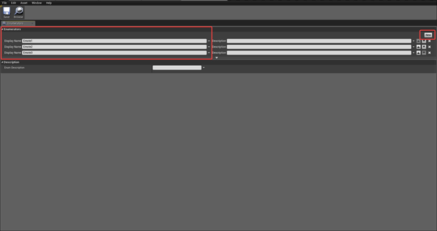
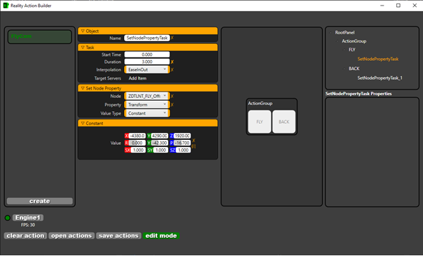 Figure 3: Reality Action Builder application. Note: You may read more about how to create actions with Action builder here. |
Answer |
|---|
Use the FILTER area to search for the specific property on the node. Do not forget to clean the filter to search for another property or to view full properties of the nodes. 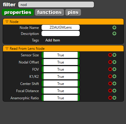 |
Answer |
|---|
Basically, it is a shrinking process on RGBA Channels separately. This node is used for overcoming the edge problems caused by spill and camera artifacts. The DILATE ALPHA node must be used. |
Answer |
|---|
There are two possible reasons if the tracking node stopped receiving data:
|
Answer |
|---|
Please go to your Tracking node, and make sure that CCD of the camera is situated in the zero point of the physical set. After making sure that the camera sensor is in zero point, you should check if moving the camera within 2 meters range to both negative and positive directions. Also the pan, tilt and roll values should be measured. For more information on track and lens calibration, please click here. |
Answer |
|---|
You might have downloaded and installed Reality without any issues via Teamviewer session. But Reality Editor requires by design that the monitor is always open and never turned off. You might choose a KVM configuration as well. |
Answer |
|---|
Yes, you can group any number of nodes regardless of their category, please refer to this tutorial for more information. |
Answer |
|---|
Yes. Just press the tab button on the keyboard and you will see the search dialog where you can start write node name and add it to your node graph more faster. This feature also saves time in navigating for a specific node across its various categories.  |
Answer |
|---|
Absolutely YES. The biggest benefit of Reality Engine is that it works with or without GPUDirect feature. Reality engine has an additional option to use GPUDirect for accelerating communication with video I/O devices. And also have the liberty to use it without the GPUDirect feature. This flexibility offers the choice to our users how they want to work with Reality engine. |
Answer |
|---|
GPUDirect is optimized pipeline for frame-based video I/O devices. The combined solution delivers the capability to maximize the performance capability of the GPUs. GPUDirect for Video is a technology that enables to take faster advantage of the parallel processing power of the GPU for image processing by permitting industry-standard video I/O devices to communicate directly with NVIDIA professional Quadro GPUs at ultra-low latency. Enabling GPUDirect in Reality engine, please refer to the link here. |
Answer |
|---|
RTX 6000 GPU include dedicated ray tracing acceleration hardware, use an advanced acceleration structure and implement an entirely new GPU rendering pipeline to enable real-time ray tracing in graphics applications. More information on Certified GPUs. For more information about Ray trace on RTX GPU, click the link: https://developer.nvidia.com/discover/ray-tracing |
Answer |
|---|
Yes. It is possible to get Fill and Key with AJA card’s physical ports with the introduction of pixel format properties. This will allow possibilities to send Fill and Key video channels over independent SDI ports from Reality as or can accept Fill and Key channels from other CG systems to use as DSK. See Fill and Key. |
Answer |
|---|
Yes. Reality 2.8 comes with a UMG based sample project with real-time data driven graphics for live football scores. JSON representation is used in the project to fetch real-time data updates. Know more about Creating and Running Data Driven template. |
Answer |
|---|
Yes. Cook Server installer is an optional installer component comes with the Reality Editor installer. More information on Cook Server installation guide. |
Answer |
|---|
Level sequencer created in other versions must be reopened in current version of Reality Editor and click on “Save”to get compiled to the current version. See Level Sequencer. |
Answer |
|---|
While using a second camera for AR pipelines to have reflection of the AR graphic on real world floor, and exclude some real areas for casting reflections on, please create a 3D model of places where you do not want to see reflections, then connect it as a separate actor for the projection and connect to showonly pin of the reflection camera as shown below. p.s. Use reflection pin of the composite passes instead of MaskedReflection pin which had been used before while using second reflection camera at AR pipelines. 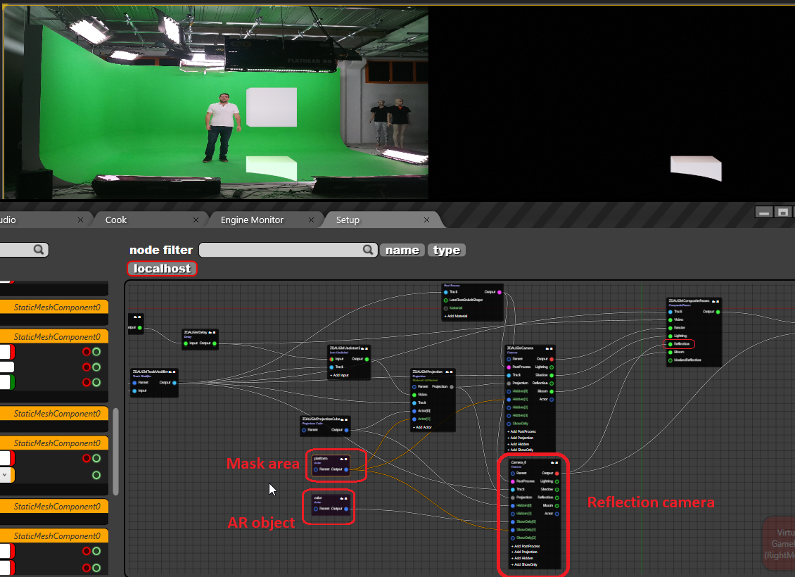 |
Answer |
|---|
By default, Reality Engine uses only 2 TCP ports (6665 and 6666) for operation, and 5561 for Cook server.
And if you have an API implementation through ActionBuilder, you can use other TCP/UDP ports according to your needs. |
Answer |
|---|
 |
Answer |
|---|
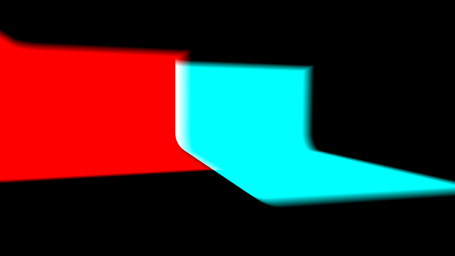
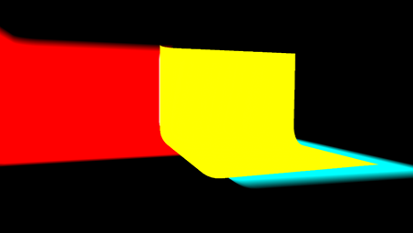
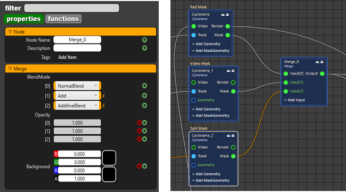
In this document you will find how to create hybrid studio rgraph. Hybrid studio configuration is a 3D Mask topic. Basically, we define the mask type according to the color of the graphic. Generally, there are 4 different colors that we can define mask areas.
In order to create Hybrid Studio please follow the instruction below.
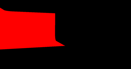 -Figure 1
 -Figure 2
 -Figure 3
 -Figure 4 The hybrid studio is almost ready, but we also need to make some adjustments in order to get ready for demonstration or On air show . There might be problems on the edges of masks. There are a couple of ways of adjusting the masks. It depends on how accurate the tracking or lens calibration is. You can change the smoothness of Cyclorama like 0.001 and/or change CleanplateFOV, or another way is opening the capture via mspaint that you took for clean plate before, extending the green area and load again under the cyclorama node. |
474px60
Answer |
|---|
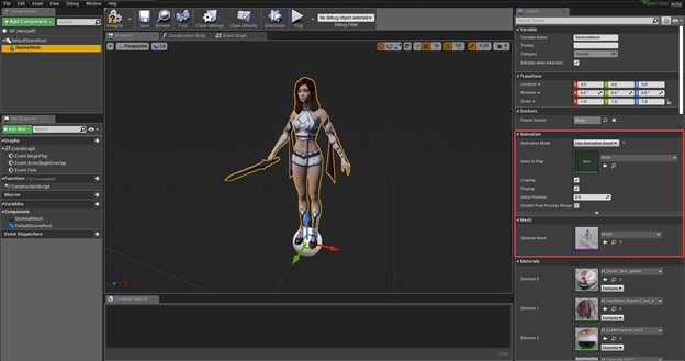
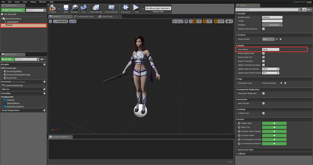
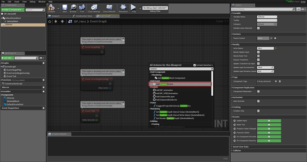
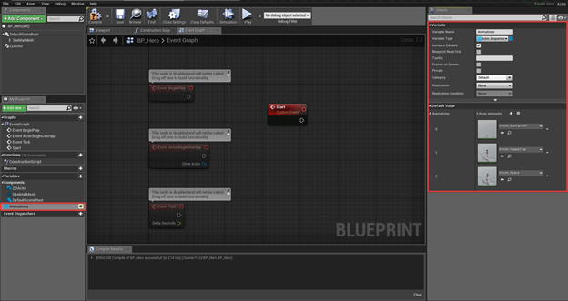
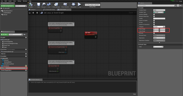
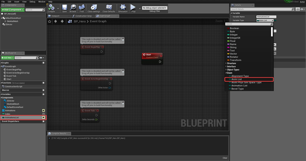
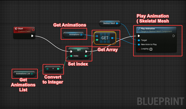
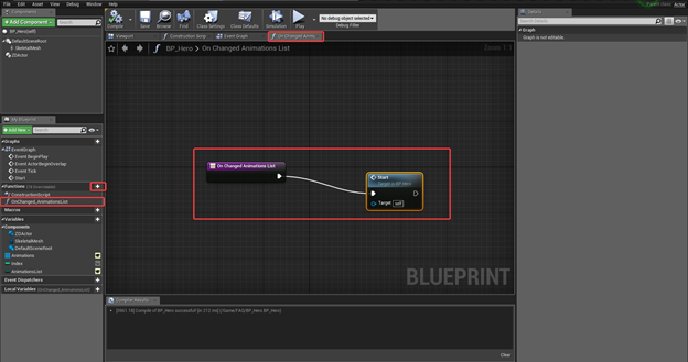
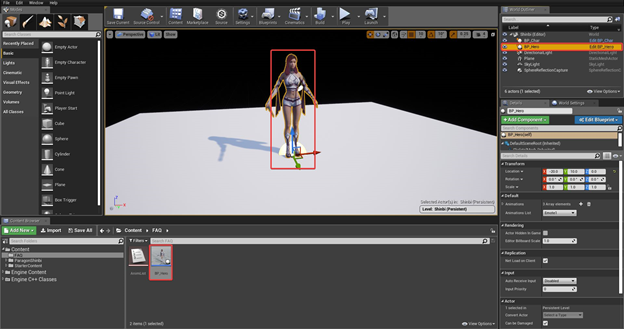
 How to Create BP_Hero Event Graph
|
Answer |
|---|
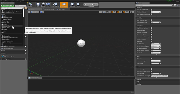
Easiest and most basic teleportation setup is possible using Billboard Node found under UE Actor Nodes. Follow the steps below to create a basic teleportation in your projects;
You have few options to give this billboard a teleportation effect.
You can see a basic Rgraph example below; 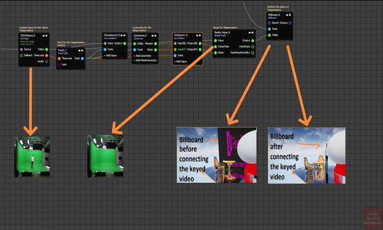 |
Answer |
|---|
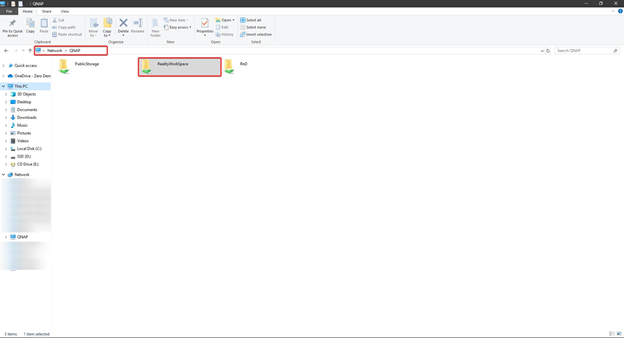
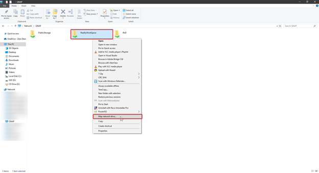
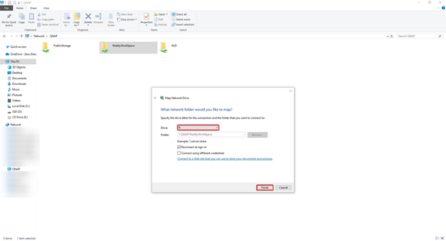
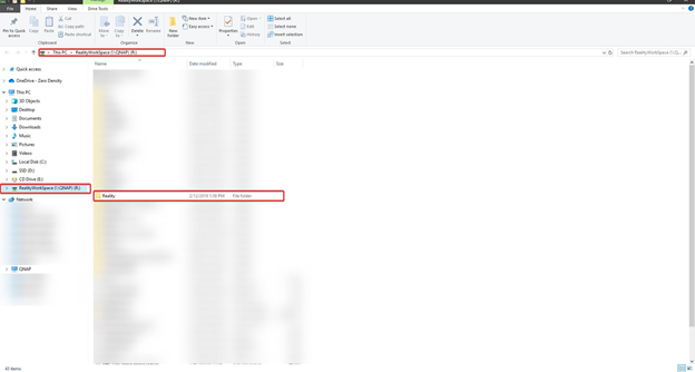
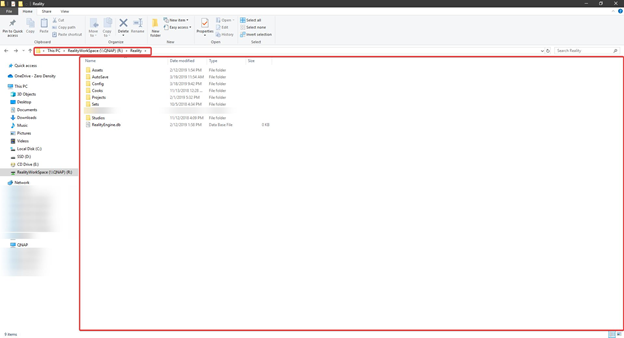
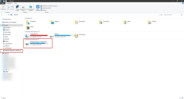 To get more detailed information about r drive configuration please visit: R Drive Mapping |
Answer |
|---|
In AJACARD node. you can open the hidden tab under Device catagory to reveal UseMultiFormat property. Enabling This Property will allow users to do do Multi-format Input-Output. 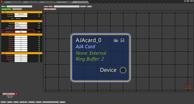 UseMultiFormat property on AjaCard Node *This feature was developed on Reality 2.9. Older versions might not support multi-format Video I/O |
Answer |
|---|
We are planning on implementing HDR in Reality 2.9 with standards ST2084(PQ) and HLG. These standards are most popularly used in the industry today. |
Answer |
|---|
There are two ways to render background separately on Reality Setup. 1st Way: It is possible to use second virtual camera to render background graphics. Connecting Projection cube to hidden pin of the virtual camera render nodes output will hide the projected video on the render and only background graphics will be rendered. This way, reflections will not get lost on the final composite output but second rendering will increase the load on the GPU. Below, there is a screenshot for this process. On Channel 1, ZDCamera node is used to project video and making final compositing. And on Channel 2, ZDCamera_0 node is used to render background graphics only. 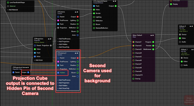 Channel1: Final Composite Output Channel2: Background Graphics 2nd Way: If losing reflections and refractions are not important for the project, it is possible to use color node with 0 Alpha instead of video on Projection node. Using this method will not project keyed talents on the 3D world and there will be no reflections or refractions of the keyed talents, but GPU load will not increase. And below, there is a screenshot for this process. Color node with 0 Alpha is connected to the Video input pin of the Projection node. Now, camera render can be used for both compositing and showing background graphics. 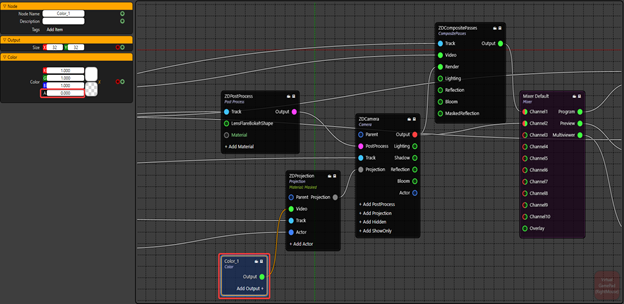 Channel1: Final Composite Output Channel2: Background Graphics |
Answer |
|---|
 You can use a TIMECODEEVENT TRIGGER node to trigger your events inside your blueprints via using the exact timecodes and queue them. TIMECODEEVENT TRIGGER node is not intended to be used through GUI, it is rather designed to be called through an API to access the values and change the values of this node. Overriding the AJA Timecode FSM is not available as this timecode is a counter of frames since the beginning of year 2000. How to add a timecode for executing a later event? 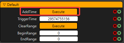 Go to Functions tab of the TIMECODEEVENT TRIGGER node and type a TriggerTime and click on EXECUTE button on AddTime as the screenshot attached. This will add this value to the queue shown in Properties of the same node. The timecode trigger clears the trigger times as soon as it has played the trigger. This is happening because of the functionality of this node. If that timecode passes and as it is past and never going to happen again, this is deleted from the queue. |
Answer |
|---|
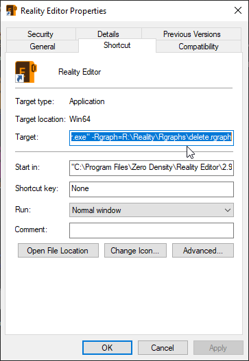
We can use the command line to run the Reality Engine project. Follow below;
“C:\ProgramFiles\ZeroDensity\RealityEditor\2.8\Engine\Binaries\Win64\UE4Editor.exe" "R:\Reality\Projects\StarterProject\StarterProject.uproject” -game
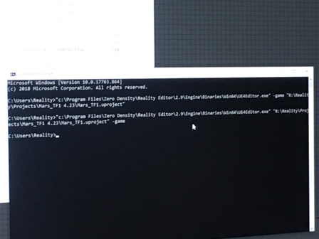 Then, it will launch Reality Engine with editor mode. |
Answer |
|---|
public void SetPropertyInt(string PropertyName, string NodeName, object Value, float StartTime, float Duration, string Interpolation) { foreach(ZDRootNodeGraph aGraph in World.NodeGraphs) { var _ IntegerProperty = new ZDProperty_Integer(PropertyName, “Default”, “”, (int)Value); aGraph.RequestSetNodeProperty(NodeName, _IntegerProperty, StartTime, Duration, Interpolation); } } |
Answer |
|---|
public void SetPropertyString(string PropertyName, string NodeName, object Value, float StartTime, float Duration, string Interpolation) { foreach(ZDRootNodeGraph aGraph in World.NodeGraphs) { var _StringProperty = new ZDProperty_String(PropertyName, “Default”, “”, (string)Value); aGraph.RequestSetNodeProperty(NodeName, _StringProperty, StartTime, Duration, Interpolation); } } |
Answer |
|---|
public void SetStringArray(string PropertyName, string NodeName, object Value, float StartTime, float Duration, string Interpolation) { ObservableCollection<string> array = new ObservableCollection<string>(); array.Add(“First1”); array.Add(“Second2”); array.Add(“Third3”); foreach(ZDRootNodeGraph aGraph in World.NodeGraphs) { var properties = aGraph.Nodes[NodeName].Properties; foreach(var prop in properties) { if(prop.MemberName == PropertyName) { ((ZDProperty_String)prop).StringValues = array; aGraph.RequestSetNodeProperty(NodeName, prop, 0, 0, “Jump”); } } } } |
Answer |
|---|
public void SetPropertyBoolean(string PropertyName, string NodeName, object Value, float StartTime, float Duration, string Interpolation) { foreach(ZDRootNodeGraph aGraph in World.NodeGraphs) { var _BooleanProperty = new ZDProperty_Boolean(PropertyName, “Default”, “”, (bool)Value); aGraph.RequestSetNodeProperty(NodeName, _BooleanProperty, StartTime, Duration, Interpolation); } } |
Answer |
|---|
public void SetPropertyFloat(string PropertyName, string NodeName, object Value, float StartTime, float Duration, string Interpolation) { foreach(ZDRootNodeGraph aGraph in World.NodeGraphs) { var _FloatProperty = new ZDProperty_Float(PropertyName, “Default”, “”, (float)Value); aGraph.RequestSetNodeProperty(NodeName, _FloatProperty, StartTime, Duration, Interpolation); } } |
Answer |
|---|
public float GetPropertyFloat(string PropertyName, string NodeName) { float value= 0.0F; foreach(ZDRootNodeGraph aGraph in World.NodeGraphs) { var properties = aGraph.nodes[NodeName].Properties; foreach(var prop in properties) { if(prop.MemberName==PropertyName) { value=((ZDCore.Model.ZDProperty_Float)prop).Value; } } } return value; } |
Answer |
|---|
public string GetPropertyString(string PropertyName, string NodeName) { string value= “”; foreach(ZDRootNodeGraph aGraph in World.NodeGraphs) { var properties = aGraph.nodes[NodeName].Properties; foreach(var prop in properties) { if(prop.MemberName==PropertyName) { value=((ZDCore.Model.ZDProperty_String)prop).Value.ToString(); } } } return value; } |
Answer |
|---|
public ZDTransform GetPropertyTransfrom(string PropertyName, string NodeName) { ZDTransform value= new ZDTransform(new ZDVector(0.0F,0.0F,0.0F), new ZDRotator(0,0,0), new ZDVector(0,0,0)); foreach(ZDRootNodeGraph aGraph in World.NodeGraphs) { var properties = aGraph.nodes[NodeName].Properties; foreach(var prop in properties) { if(prop.MemberName==PropertyName) { value=((ZDCore.Model.ZDProperty_Transform)prop).Value; } } } return value; } |
Answer |
|---|
public bool GetPropertyBoolean(string PropertyName, string NodeName) { bool value= false; foreach(ZDRootNodeGraph aGraph in World.NodeGraphs) { var properties = aGraph.nodes[NodeName].Properties; foreach(var prop in properties) { if(prop.MemberName==PropertyName) { value=((ZDCore.Model.ZDProperty_Boolean)prop).Value; } } } return value; } |
public void GetPropertyInteger(string PropertyName, string NodeName) { int value= 0; foreach(ZDRootNodeGraph aGraph in World.NodeGraphs) { var properties = aGraph.nodes[NodeName].Properties; foreach(var prop in properties) { if(prop.MemberName==PropertyName) { value=((ZDCore.Model.ZDProperty_Integer)prop).Value; } } } return value; } |
Answer |
|---|
public void SetPropertyTransform(string PropertyName, string NodeName, object Value, float StartTime, float Duration, string Interpolation) { foreach(ZDRootNodeGraph aGraph in World.NodeGraphs) { var _TransformProperty = new ZDProperty_Transform(PropertyName, “Default”, “”, (ZDTransform)Value); aGraph.RequestSetNodeProperty(NodeName, _TransformProperty, StartTime, Duration, Interpolation); } } |
Answer |
|---|
|
Answer |
|---|
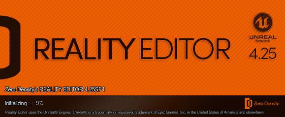 Figure 1: Learning the current version of Reality (Unreal) Editor 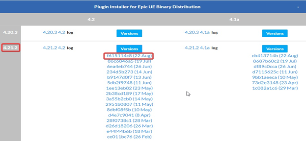 Figure 2: Choosing the correct version of plug-in
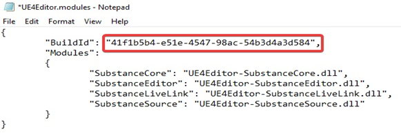 Figure 3: Build ID
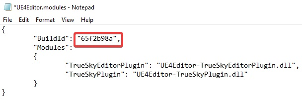 Figure 4: Before the change of Build ID 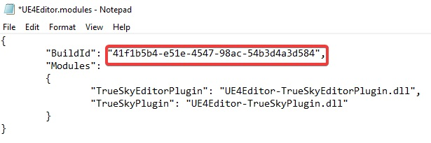 Figure 5: After the change of Build ID 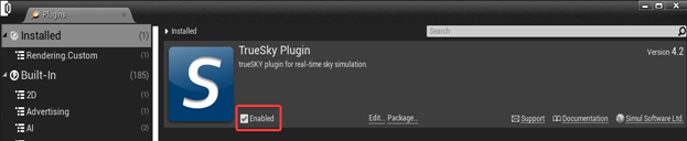 Figure 6: Enable the plug-in(s) |