Below you can find short answers for frequently asked questions, improving your everyday Reality knowledge and allow you to use Reality in the best possible way. Some of the answers have links that can lead you to in-depth documentation for that topic.
Can I use the Cleanplates of Cyclorama in another engine?
Answer
Since the Reality has Image Based Keyer, the image that is taken from a specific camera, with a specific lens which might has a different Lens Center Shift Value will differ in each separate system. We recommend that you take the clean plates separately for each engine to make sure that you get the best result from each engines.
I have different lighting setups in my studio. Which lighting is the best to take clean plates for Cyclorama?
Answer
As Reality uses Image Based keying, it is important to take the captures to be used as Clean plates while you have the general lighting. It is advised to test and compare the result and to take specific captures for Clean plates if you observe a drastic change in the keying quality when you change the lighting setup in your physical studio. But if you are using just talent lighting in close shots, this might night be a need. Please visit the following topic: What is Image Based Keying?
How to use FlyCam
Answer
This is a step-by-step guide to make FlyCam virtual camera movement\s including a sample action file.
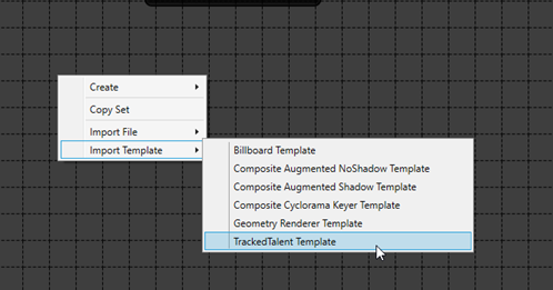
Launch your studio and from Reality Control applications open Reality Setup, right-click and select Import Template > TrackedTalent Template.
Figure 1: Reality Setup application.
Prepare the Video I/O setup by adding AJA Card and AJA Out nodes and selecting the input and output ports accordingly.
If you have a camera tracking system, replace ZDTLNT_CameraTrack node with a relevant tracking node.
Define the cyclorama size, location and add capture under the function tab of the cyclorama node.
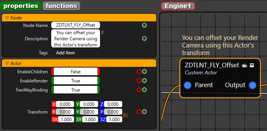
In the ZDTLNT_FLY_Offset node modify the Transform values to define the FlyCam position.
Figure 2: Custom Actor node for Fly Offset and its properties.
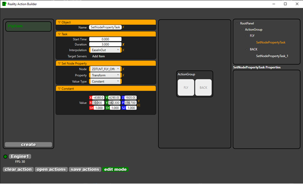
Once you decide the position to fly to, open Reality Action Builder application (press F6 if you launched the studio from Launcher, or go to C:\Program Files\Zero Density\Reality Control Applications\2.x\ZDRealityActionBuilder.exe if you have run the project directly from the Reality Editor), and open the sample file below.
Under the Action “FLY” select “SetNodePropertyTask” and enter the FlyCam position, the flight duration and the interpolation. In our sample action file, the duration is set to 3 seconds and the interpolation is EaseInOut. Please note that “BACK” action has a duration of 2 seconds and the Transform value is set to “0”.
Figure 3: Reality Action Builder application.
Note: You may read more about how to create actions with Action builder here.
What is DilateRGBA node? How can i use it?
Answer
Basically, it is a shrinking process on RGBA Channels separately. This node is used for overcoming the edge problems caused by spill and camera artifacts. The DILATE ALPHA node must be used.
We have finished the tracking device setup in our studio. How can we make sure if the tracking is well calibrated?
Answer
Please go to your Tracking node, and make sure that CCD of the camera is situated in the zero point of the physical set. After making sure that the camera sensor is in zero point, you should check if moving the camera within 2 meters range to both negative and positive directions. Also the pan, tilt and roll values should be measured. For more information on track and lens calibration, please click here.
I am connected to my device via Teamviewer and why doesn`t Reality Editor launch?
Answer
You might have downloaded and installed Reality without any issues via Teamviewer session. But Reality Editor requires by design that the monitor is always open and never turned off. You might choose a KVM configuration as well.
What is GPUDirect and how to enable it in Reality Engine?
Answer
GPUDirect is optimized pipeline for frame-based video I/O devices. The combined solution delivers the capability to maximize the performance capability of the GPUs. GPUDirect for Video is a technology that enables to take faster advantage of the parallel processing power of the GPU for image processing by permitting industry-standard video I/O devices to communicate directly with NVIDIA professional Quadro GPUs at ultra-low latency. Enabling GPUDirect in Reality engine, please refer to the link here.
Does Reality Engine support hardware Fill and Key?
Answer
Yes. It is possible to get Fill and Key with AJA card’s physical ports with the introduction of pixel format properties. This will allow possibilities to send Fill and Key video channels over independent SDI ports from Reality as or can accept Fill and Key channels from other CG systems to use as DSK.
Does Reality Engine support Real-time Data driven graphics?
Answer
Yes. Reality Engine comes with a UMG basedsample project with real-time data driven graphics for live football scores. JSON representation is used in the project to fetch real-time data updates.
Why cant I see Level Sequencer option in Create menu on node graph?
Answer
Level sequencer created in other versions must be reopened in current version of Reality Editor and click on "Save" to get compiled to the current version.
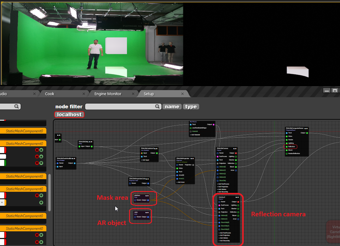
While using a second camera for AR pipelines to have reflection of the AR graphic on real world floor, and exclude some real areas for casting reflections on, please create a 3D model of places where you do not want to see reflections, then connect it as a separate actor for the projection and connect to showonly pin of the reflection camera as shown below.
Use REFLECTION pin of the COMPOSITE PASSES instead of MASKEDREFLECTION pin which had been used before while using second reflection camera at AR pipelines.
How to Create Hybrid Studio Rgraph?
Answer
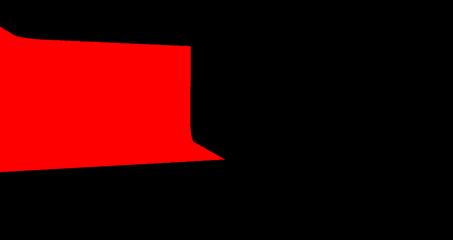
In this document you will find how to create hybrid studio rgraph. Hybrid studio configuration is a 3D Mask topic. Basically, we define the mask type according to the color of the graphic. Generally, there are 4 different colors that we can define mask areas.
Black: Only graphic
Cyan: Video output
Red: Keying area
Yellow: Spill suppression
In order to create Hybrid Studio please follow the instruction below. Create a Keyed Cyclorama nodegraph. Go to CYCLORAMA node, click on the ADDPROJECTION under FUNCTIONS tag after you done with measuring dimensions of cyclorama. If you have any doubt about that please click here.
If you connect the mask pin of Cyclorama to Video mixer channel you will see the mask output as in figure1 which means this area will be keyed, if model or object get into greenbox. Black area will be full graphic.
-Figure 1
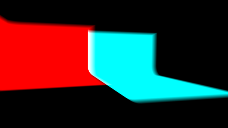
We define the borders of our virtual environment. Now it is time to define the real area. In order to do that create a new cyclorama node. Change the mask color as Cyan. Now, we have two different mask types in our configuration, we need to merge them with Merge Node. You will see the two different masks in channel output when you merge them. Change the transform values of Video mask cyclorama and bring it near to the first cyclorama. You can follow various scenarios depending on your real studio configuration.
-Figure 2
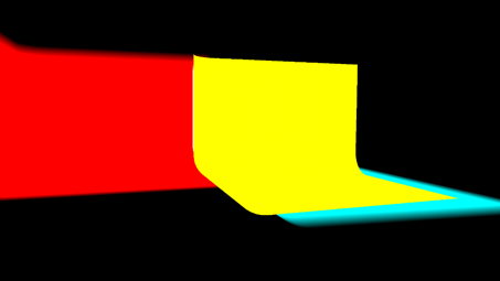
Most probably you will see green spill on the output. To get rid of this, duplicate the Video mask Cyclorama and change the mask color to yellow. Just like Cyan mask you need to connect mask pin to Merge Node.
-Figure 3
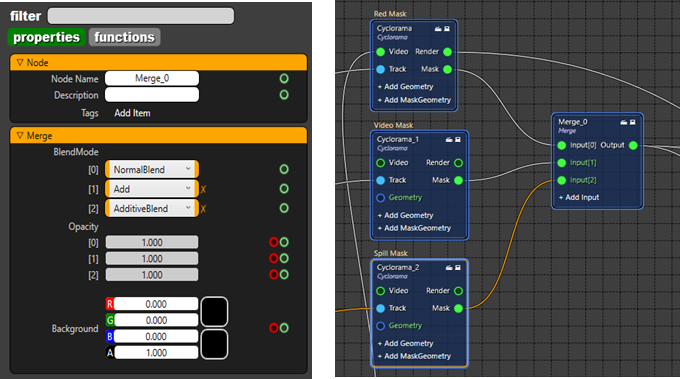
Merge mode properties and mask connections must look like to Figure4.
-Figure 4
The hybrid studio is almost ready, but we also need to make some adjustments in order to get ready for demonstration or On air show . There might be problems on the edges of masks. There are a couple of ways of adjusting the masks. It depends on how accurate the tracking or lens calibration is. You can change the smoothness of Cyclorama like 0.001 and/or change CleanplateFOV, or another way is opening the capture via mspaint that you took for clean plate before, extending the green area and load again under the cyclorama node.
How to create animation list and play them from blueprints?
474px60
Answer
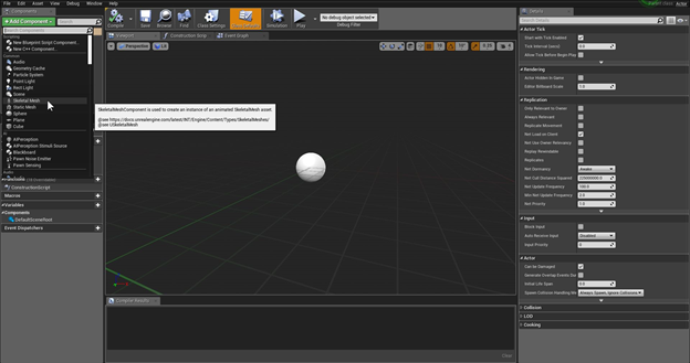
Create a blueprint actor in your project and add a skeletal mesh component to your blueprint
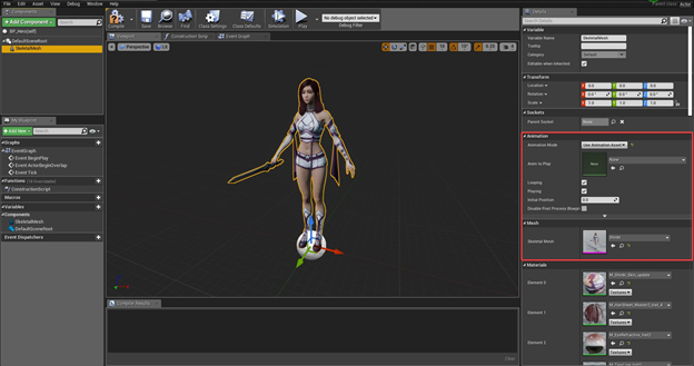
Select the Skeletal Mesh and select “Use Animation Asset” on Animation mode
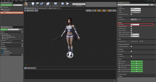
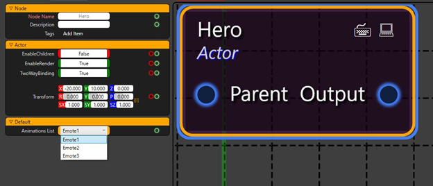
Add ZDACTOR Component and name how your Blueprint will appear on Reality Setup (We’ll call this Hero)
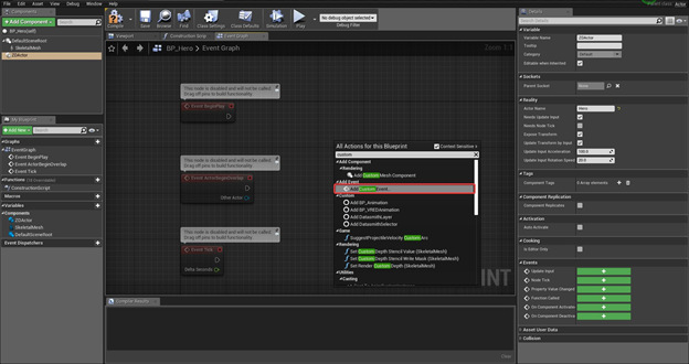
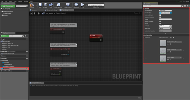
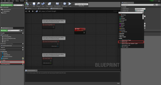
Add a Custom Event On Event Graph (We’ll call this event START)
Create a variable and select Anim Sequence Base object reference as Variable type and make this variable an Array. Make this variable public and compile your blueprint. After these steps select your animations on the Default value part of this Variable (We’ll call this variable Animations)
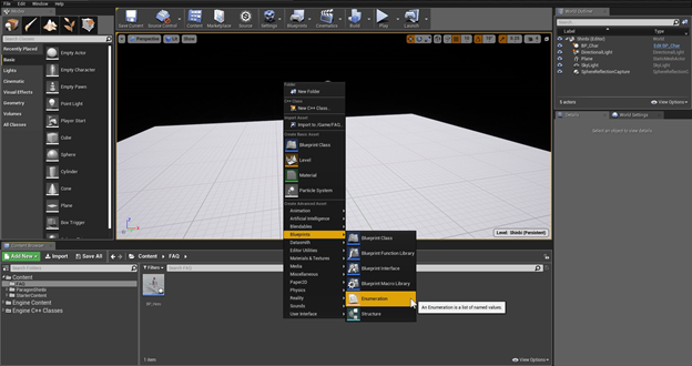
Compile and Save your Blueprint and return to the content Browser of your Project. Create an Enumaration under Blueprints Tab. (We’ll call this AnimList)
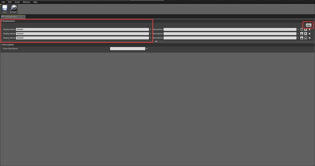
Open the created Enumeration and by clicking the ``New`` button on top right side of the window, create a list and Name all the Animations that you have. Keep in mind that these will be visible to user on Reality Setup. After you are finished, save close the Enumeration. (Our Animation names are Emote1, Emote2 and Emote3)
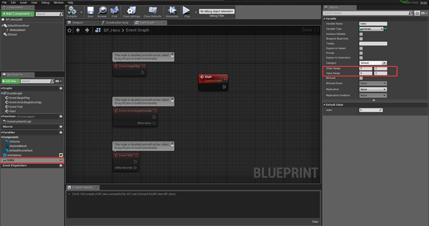
Now open your Blueprint again create an Integer to select which index of your animations and Enumeration will be played. This variable does not have to be public. And for a better use, adjust the slider range and Value Range of your Integer. If you have 3 Animations like this example, you can select 0 – 2 for your parameters. Compile your blueprint again.
Create a new Variable, make it Public, Select the name of the Enumeration List you created under Enum Tab from Variable Type and Compile your Blueprint. You should be able to see the list you created as a dropdown list on your Variable.
Create the Event Graph as Shown Below. Compile and Save the Blueprint. For detailed step-by-step creation of this event graph, see the end of this document.
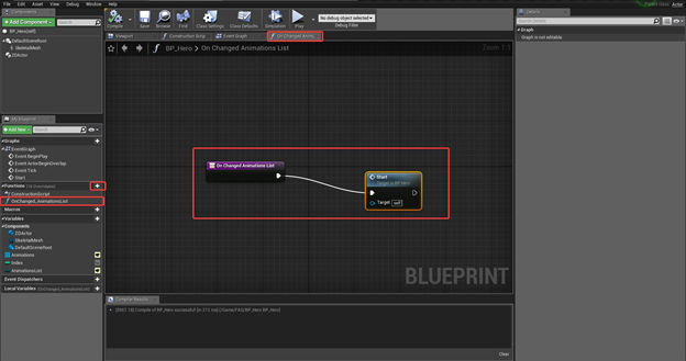
Create a new function and name it OnChanged_AnimationsList. Right click on an empty space on the On Changed Animations List window and select “Call Function → Start” and connect the node to On Changed Animations List Node. Now, Compile, Save and close the blueprint.
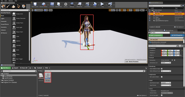
Drag this blueprint to the project and it should be visible on World Outliner.
Press Play. You should be able to see the multiviewer screen of Reality. Now open Reality Setup Application. You should see The Hero Node automatically created and when you click on this node, you can select the animation to play under Default → Animations List as a dropdown list.
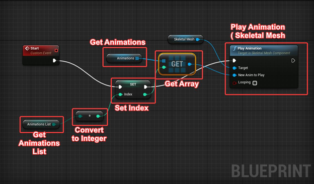
How to Create BP_Hero Event Graph
Drag and drop AnimationsList Enum variable to the Event Graph Window and Select “Get AnimationsList”
Click and drag the output pin of the Animations List reference and choose Math → Conversions → ToInt (Byte)
Drag and Drop Index Variable to the Event Graph Window and Select “Set Index”
Connect Exec output of the Start Event to the Set Index Node
Connect Animations Lists Converted Integer Output to the Integer Input of the Set Index Node
Drag and Drop Animations Anim Sequence Base Variable to the Event Graph Window and Select “Get Animations”
Click and drag the output pin of the Animations reference and Choose “Utilities → Array → Get (a copy)”
Connect the INTEGER output pin of SET INDEX node to the GET ANIMATION node's INTEGER input pin
Click and drag the Exec output pin of the Set Node and Choose ``Components>Animation>Play Animation (SkeletalMesh)``
Connect the output of Get Animations Node to “New Anim to Play” Input of “Play Animation” Node.
Enable or disable Looping on ”Play Animation” Node
How to make a basic teleportation with Reality Setup?
Answer
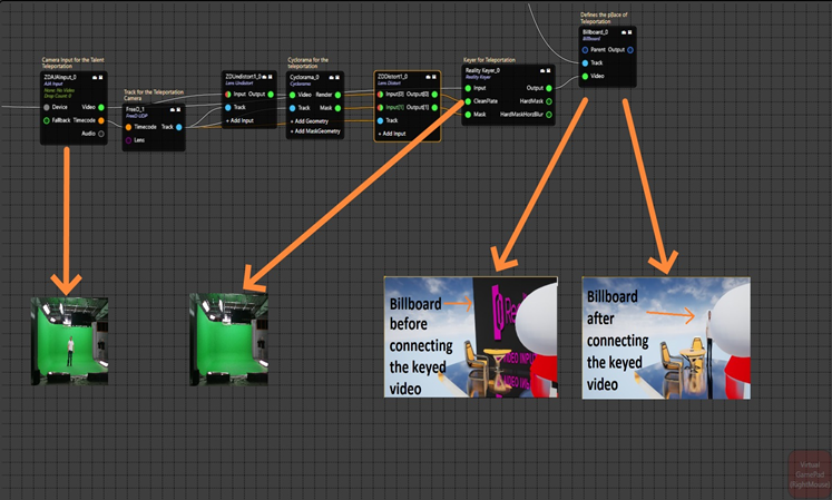
Easiest and most basic teleportation setup is possible using Billboard Node found under UE Actor Nodes. Follow the steps below to create a basic teleportation in your projects;
You need to key the talent separately you’re willing to teleport and feed this keyed video to the Video pin of the billboard node.
Connect tracking pin of the billboard node to your real tracking.
Enable “TalentFacing” property of your billboard node so that virtual billboard will face the camera no matter where your camera moves.
Position this Billboard to the desired location in your project.
You have few options to give this billboard a teleportation effect.
You can Enable and disable its ``EnableRender`` property for an instant appearance and disappearance of your talent
You can change the scale of the billboard for giving a stretching effect.
You can change the transform values of the billboard node to give it a sliding effect.
You can even combine these methods to get the best result that suits your project the most.
You can see a basic Rgraph example below;
How to do Multi-Format video IO with Reality?
Answer
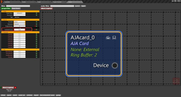
In AJACARD node. you can open the hidden tab under Device catagory to reveal UseMultiFormat property. Enabling This Property will allow users to do do Multi-format Input-Output.
UseMultiFormat property on AjaCard Node
*This feature was developed on Reality 2.9. Older versions might not support multi-format Video I/O
How to render background graphics only?
Answer
There are two ways to render background separately on Reality Setup.
1st Way:
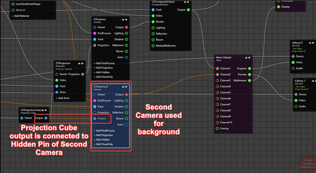
It is possible to use second virtual camera to render background graphics. Connecting Projection cube to hidden pin of the virtual camera render nodes output will hide the projected video on the render and only background graphics will be rendered.
This way, reflections will not get lost on the final composite output but second rendering will increase the load on the GPU.
Below, there is a screenshot for this process. On Channel 1, ZDCamera node is used to project video and making final compositing. And on Channel 2, ZDCamera_0 node is used to render background graphics only.
Channel1: Final Composite Output
Channel2: Background Graphics
2nd Way:
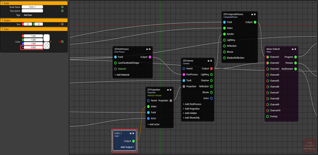
If losing reflections and refractions are not important for the project, it is possible to use color node with 0 Alpha instead of video on Projection node. Using this method will not project keyed talents on the 3D world and there will be no reflections or refractions of the keyed talents, but GPU load will not increase.
And below, there is a screenshot for this process. Color node with 0 Alpha is connected to the Video input pin of the Projection node. Now, camera render can be used for both compositing and showing background graphics.
Channel1: Final Composite Output
Channel2: Background Graphics
How can I use Timecode Event Trigger node and its functionality?
Answer
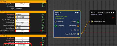
You can use a TimeCodeEventTrigger node to trigger your events inside your blueprints via using the exact timecodes and queue them. TimeCodeEvent Trigger node is not intended to be used through GUI, it is rather designed to be called through an API to access the values and change the values of this node. Overriding the AJA Timecode FSM is not available as this timecode is a counter of frames since the beginning of year 2000.
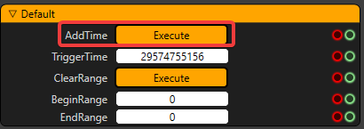
How to add a timecode for executing a later event?
Go to Functions tab of the TimeCodeEventTrigger node and type a TriggerTime and click on “Execute” button on AddTime as the screenshot attached. This will add this value to the queue shown in Properties of the same node. The timecode trigger clears the trigger times as soon as it has played the trigger. This is happening because of the functionality of this node. If that timecode passes and as it is past and never going to happen again, this is deleted from the queue.
How to run your project using command prompt on Editor mode?
Answer
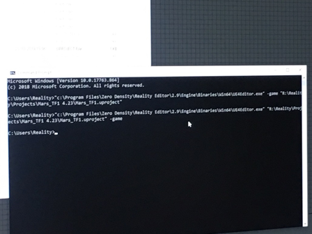
We can use the command line to run the Reality Engine project.
Follow below;
Press the Windows button and write Command Prompt on the search tab.
Write below command on the command line. You should be modified your command according to your installation and project folder structure.
You can download the “ActionforVideoWall.mp4” file from this document. In this video, you will see the how to prepare an action which changed the dynamically file path of video wall using the media input node, step by step.
Also, you can download the VIDEO.raction file and modify it.
How to use 3rd party plugin in Reality Editor?
Answer
Please make sure the plug-in and Reality Editor version you are using are compatible (same). You can follow these steps to learn your version of Reality Editor.
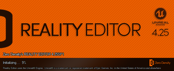
Please open the Reality Editor
You can see “Reality Editor X.X.X. based on Unreal Editor Y.Y.Y”
Figure 1: Learning the current version of Reality (Unreal) Editor
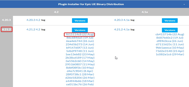
Figure 2: Choosing the correct version of plug-in
Please download and install the 3rd party plug-in(s) to “C:\Program Files\Zero Density\Reality Editor”
After the installation, you need the change Build Id of plug-in(s) with manually.
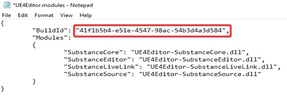
Please go to the “C:\Program Files\Zero Density\Reality Editor\Engine\Plugins\Marketplace\Substance\Binaries\Win64”
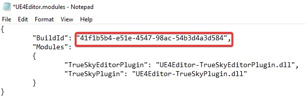
Right click to “UE4Editor.modules” and open with Notepad
Copy to “BuildId”
Figure 3: Build ID
Please go to the “C:\Program Files\Zero Density\Reality Editor\Engine\Plugins” and locate your new plug-in(s)
After the locate folder(s)
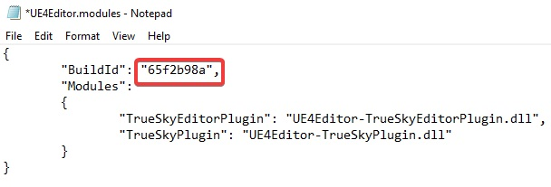
Please go to the “C:\Program Files\Zero Density\Reality Editor\Engine\Plugins\XXXXX\Binaries\Win64”
Right click to “UE4Editor.modules” and open with Notepad
Paste/change to “BuildId” and save it
If you have more than one plug-in(s), you need to repeat these steps for all of them
Figure 4: Before the change of Build ID
Figure 5: After the change of Build ID
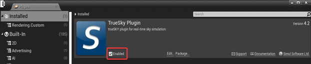
Figure 6: Enable the plug-in(s)
JavaScript errors detected
Please note, these errors can depend on your browser setup.
If this problem persists, please contact our support.